Vision Transformers Need Registers
An interactive field guide
Why do some image positions become global scratch space? Follow the evidence, then trace the added tokens.
Before this article: ViT · Semantic representations
What was already possible
Section titled “What was already possible”A patch token can stop behaving like a patch
Section titled “A patch token can stop behaving like a patch”A ViT starts with one vector per image patch. After attention, each vector can contain information from the whole image. A grid-shaped output therefore does not guarantee that every position preserves its original local pixels. CLS is a separate learned readout token. A register is another learned input vector, intended to provide internal workspace.
DINO learns visual representations by matching teacher and student predictions across image views. CLIP-style methods align images with text; DeiT uses class labels. Registers are an architectural addition that the paper studies across these training objectives. They are not a new self-supervised loss or a quantization codebook.
What changes, and why
Section titled “What changes, and why”Read from left to right. Select a module to connect its role, tensor shape, and calculation. Snippets are teaching pseudocode. Sources provide the paper method or audited implementation.
Insert learned registers into the shared encoder
Let N be the number of patches, D the feature width and R the number of registers. The input has N+R+1 positions. Register initial values are shared across images, but their activations change with each image through attention. The same Transformer blocks process CLS, registers and patches together.
z = concat(cls, patch_embed(image))
z = z + interpolated_positions
z = concat(z[:, :1], registers, z[:, 1:])
z = transformer(z)
Training state: Static source inspection; training state is discussed below.
Step-by-step explanation: Insert learned registers into the shared encoder
Discard workspace outputs, not image positions
After the final normalization, CLS is at index 0, registers occupy [1,1+R), and image patches occupy [1+R,N+R+1). Only patch features should be reshaped into the spatial grid. Including register vectors in this reshape breaks the correspondence between sequence indices and image positions.
normalized = norm(z)
cls = normalized[:, 0]
reg = normalized[:, 1:1+R]
patch = normalized[:, 1+R:]
image_grid = patch.reshape(B, H_patch, W_patch, D)
Training state: Static source inspection; training state is discussed below.
Step-by-step explanation: Discard workspace outputs, not image positions
The evidence behind the workspace hypothesis
Section titled “The evidence behind the workspace hypothesis”The paper finds a small set of high-norm output patch vectors. In the analyzed DINOv2-g case, 2.37% exceed a chosen norm threshold of 150. This threshold is a diagnostic choice for that model. It is not a universal detector. The outliers often correspond to locally redundant background patches.
Linear probes provide two separate observations: outlier tokens recover local position and pixels less well, but predict image-level labels better than ordinary patches. The authors interpret this as reuse of spatial positions for global computation. This is an explanation supported by experiments, not a proof that every large-norm vector is harmful.
Norm and attention are different quantities. Q/K projections, normalization and vector direction also affect attention. Smooth feature maps and better task scores must be checked separately.
Insert learned registers into the shared encoder
Section titled “Insert learned registers into the shared encoder”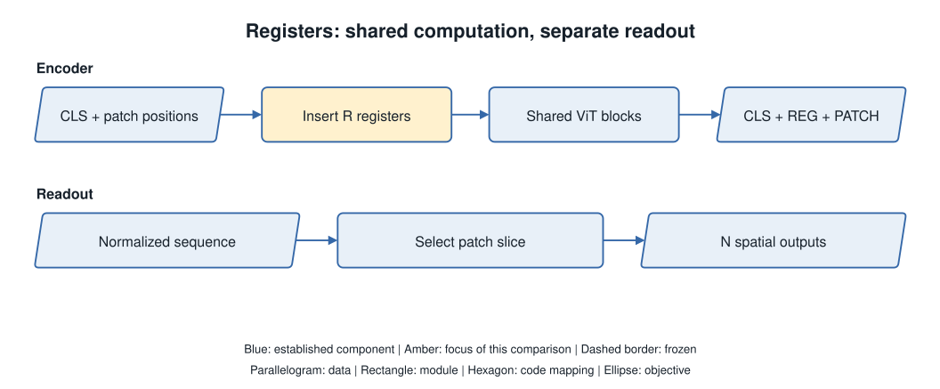
Let N be the number of patches, D the feature width and R the number of registers. The input has N+R+1 positions. Register initial values are shared across images, but their activations change with each image through attention. The same Transformer blocks process CLS, registers and patches together.
In the pinned DINOv2 code, absolute positions are first added to CLS and patches. Registers are then inserted after CLS. The paper figure draws a different token order; the code order is used in this walkthrough. Existing memory-token work already supplied the general mechanism. This paper adds the visual diagnosis and controlled evidence for this remedy.
z = concat(cls, patch_embed(image))
z = z + interpolated_positions
z = concat(z[:, :1], registers, z[:, 1:])
z = transformer(z)- Pinned DINOv2 implementation — prepare_tokens_with_masks
Work through the mechanism
Section titled “Work through the mechanism”Discard workspace outputs, not image positions
Section titled “Discard workspace outputs, not image positions”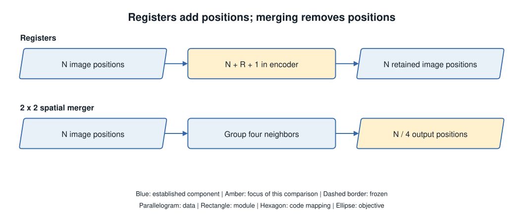
After the final normalization, CLS is at index 0, registers occupy [1,1+R), and image patches occupy [1+R,N+R+1). Only patch features should be reshaped into the spatial grid. Including register vectors in this reshape breaks the correspondence between sequence indices and image positions.
For 256 patches and four registers, the encoder processes 261 positions and returns the same 256-position image grid. Four width-768 input vectors add 3072 parameters. The attention-score matrix grows from 257² to 261² entries per head. This small calculation does not include projections, MLPs or hardware effects.
normalized = norm(z)
cls = normalized[:, 0]
reg = normalized[:, 1:1+R]
patch = normalized[:, 1+R:]
image_grid = patch.reshape(B, H_patch, W_patch, D)
Add workspace; keep the image grid
Analytical example: 16×16=256 patches, width 768, and one CLS. Change the register count to inspect sequence structure and attention-score entries. This does not simulate feature quality or training.
| Quantity | Result |
|---|---|
| Backbone sequence length | 261 |
| Retained image positions | 256 |
| Python patch slice | [:, 5:261, :] |
| Added learned parameters | 3072 |
| Attention-score entries per head | 68121 |
| Entry ratio to R=0 | 1.0314 |
The output slice follows the pinned DINOv2 order: CLS → REG → PATCH. The cost ratio applies only to the attention matrix, not total FLOPs or latency.
Training is not sampling
Section titled “Training is not sampling”Train with the changed sequence; inspect the actual controls
Section titled “Train with the changed sequence; inspect the actual controls”The experiments train models with registers. Appending untrained vectors to an existing checkpoint is not the reported procedure. The study uses DeiT-III ViT-B and DINOv2 ViT-L on ImageNet-22k, and OpenCLIP ViT-B/16 on a licensed Shutterstock image–text corpus. These are different training settings.
Most experiments use four registers; the count ablation includes 0, 1, 2, 4, 8 and 16. The appendix also enables antialiasing for DINOv2 position interpolation. A faithful comparison records this setting, the backbone size, training data, readout type and downstream protocol. A register-count slider cannot reproduce these training runs.
Reported evidence, not a local reproduction
Section titled “Reported evidence, not a local reproduction”| Setting | Metric | Value | Interpretation |
|---|---|---|---|
| DINOv2 → +reg, Table 2 | ADE20k mIoU | 46.6 → 47.9 | Frozen-feature linear evaluation |
| DINOv2 → +reg, Table 3 | VOC2007 CorLoc | 35.3 → 55.4 | LOST |
| OpenCLIP → +reg, Table 3 | VOC2007 CorLoc | 38.8 → 37.1 | A counterexample to universal improvement |
What this does not establish
Section titled “What this does not establish”What this changes for reconstruction research
Section titled “What this changes for reconstruction research”LOST object discovery improves for DINOv2 but becomes slightly worse for OpenCLIP in the reported comparison. Removing artifacts is therefore not a guarantee of universal gains. The local linear pixel probe is not a full image decoder. The paper does not establish that registers improve RAE reconstruction.
For UAR, first check which tokens the frozen encoder returns and which positions the decoder reads. Then test a matched encoder/decoder comparison if needed. Registers are not TiTok compressed latent slots: this design keeps the original patch grid and adds internal positions.
Check your understanding
Section titled “Check your understanding”Does discarding register outputs mean they did no work?
No. They exchange information through all shared blocks before the output selection.
Sources and next steps
Section titled “Sources and next steps”- Vision Transformers Need Registers · 2309.16588v2
- Method / pinned implementation source
- Visual tokenizers in multimodal models
Original teaching diagrams and snippets are identified separately from attributed paper figures. Paper reports, implementation observations, and analytical examples are distinguished. No research model runs in this page.